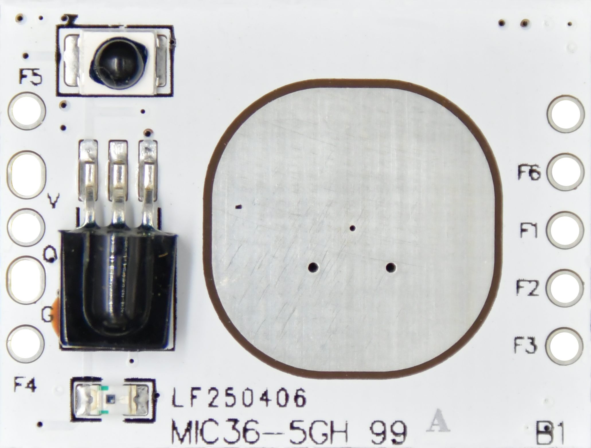
| MIC36-5GH 99 A | MIC36-5GH 99 B | MIC36-5GH 99 C | MIC36-5GH 99 D | ||
| Input | Rated Voltage | 5-13Vdc | 12±1Vdc | 8-13Vdc | 3.3Vdc |
| Working Current | 5±2mA | ||||
| Ripple Voltage | <120mVp-p | ||||
| Output | Output Signal | 3.3V high and low level signals, 1kHz PWM dimming signal | 0/1-10Vdc dimming signal | 5V high and low level signals, 1kHz PWM dimming signal | 3.3V high and low level signals, 1kHz PWM dimming signal |
| Sensor Parameters | Operating Frequency | 5.8GHz ±75MHz, ISM band | |||
| Transmission Power | 1mW Max. | ||||
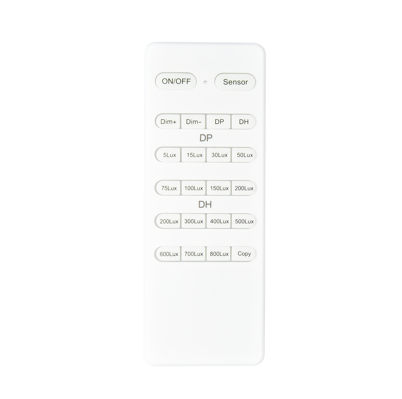
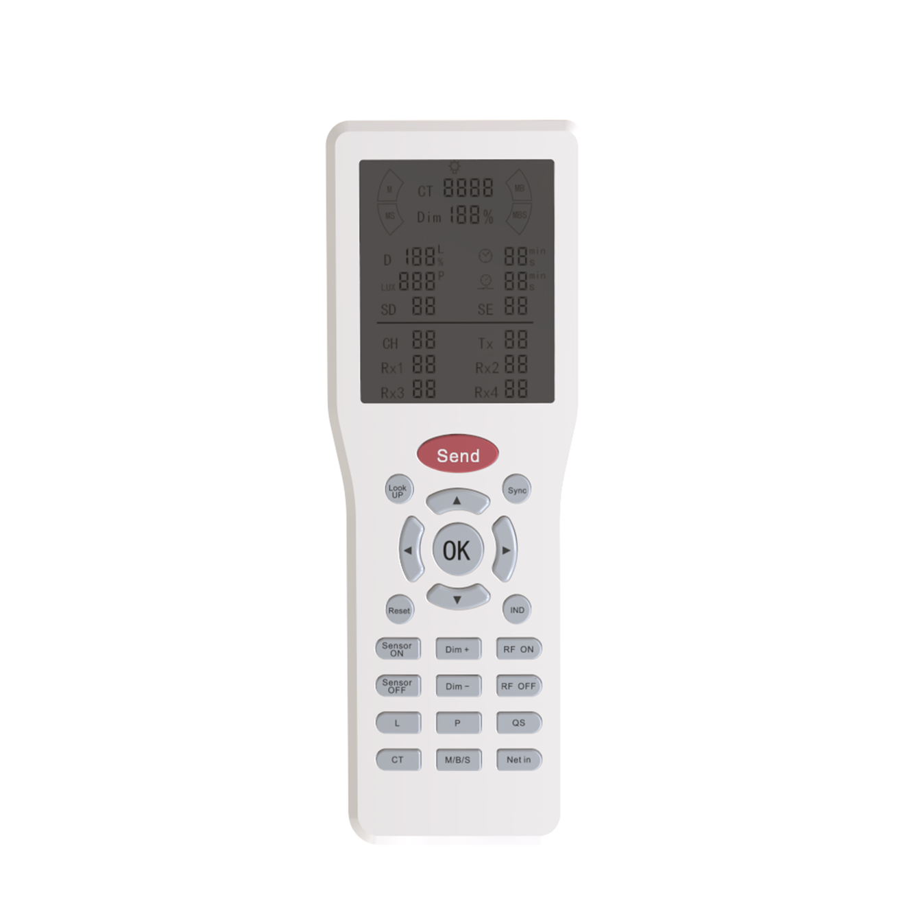
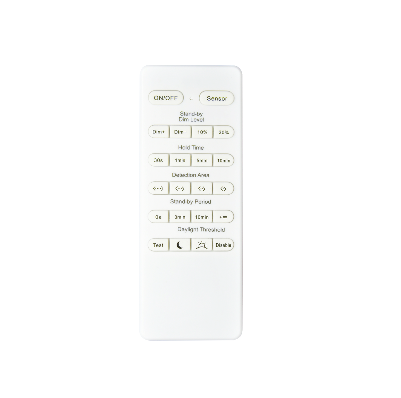
| Detection Area | 25% / 50% / 75% / 100% MH16 and MH10 Remote control settings |
||||
| Hold Time | External dialing for parameter setting: 5s/30s/3min/5min/10min/20min (see dialing function table for details) MH16 and MH10 remote control settings |
||||
| Daylight Sensor | Normal daylight: | External dialing code for parameter setting: 5Lux / 25Lux / 50Lux / Disable MH16、MH10 Remote control settings |
|||
| Daylight priority: | Switch ON | Switch OFF | |||
| 5Lux | Switch on value + (50-100Lux) | ||||
| 25Lux | Switch on value +(50-100Lux) | ||||
| 50Lux | Switch on value + (50-100Lux) | ||||
| Stand-by Period | External dialing for parameter setting: 0s/30s/10min/+∞ MH16 and MH10 remote control settings |
||||
| Stand-by Dim Level | External dialing for parameter setting: 20%/30% MH16、MH10 Remote control settings |
||||
| Detection Range (radius) | Ceiling installation 3m high | ||||
| Human body sensing: r≥ 3.5m@0.3m/s, r≥ 3m@1m/s | |||||
| Test conditions: The product sensing range is set to 100%, and the testing site is an indoor space of 60㎡ | |||||
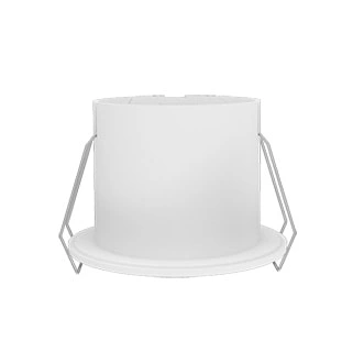
| Installing Height | 3m (6m Max.) | ||||
| Environment | Working Environment Temperature | -25~85℃ | |||
| Storage Temperature | 20℃~30℃, Humidity ≤ 60% (non condensing) | ||||
| Certification Standards | Compliant with Certification | CE, RED, FCC | |||
| Environmental Requirements | Compliant with RoHS 2.0 and Reach requirements | ||||
| Protection Grade | IP00 | ||||
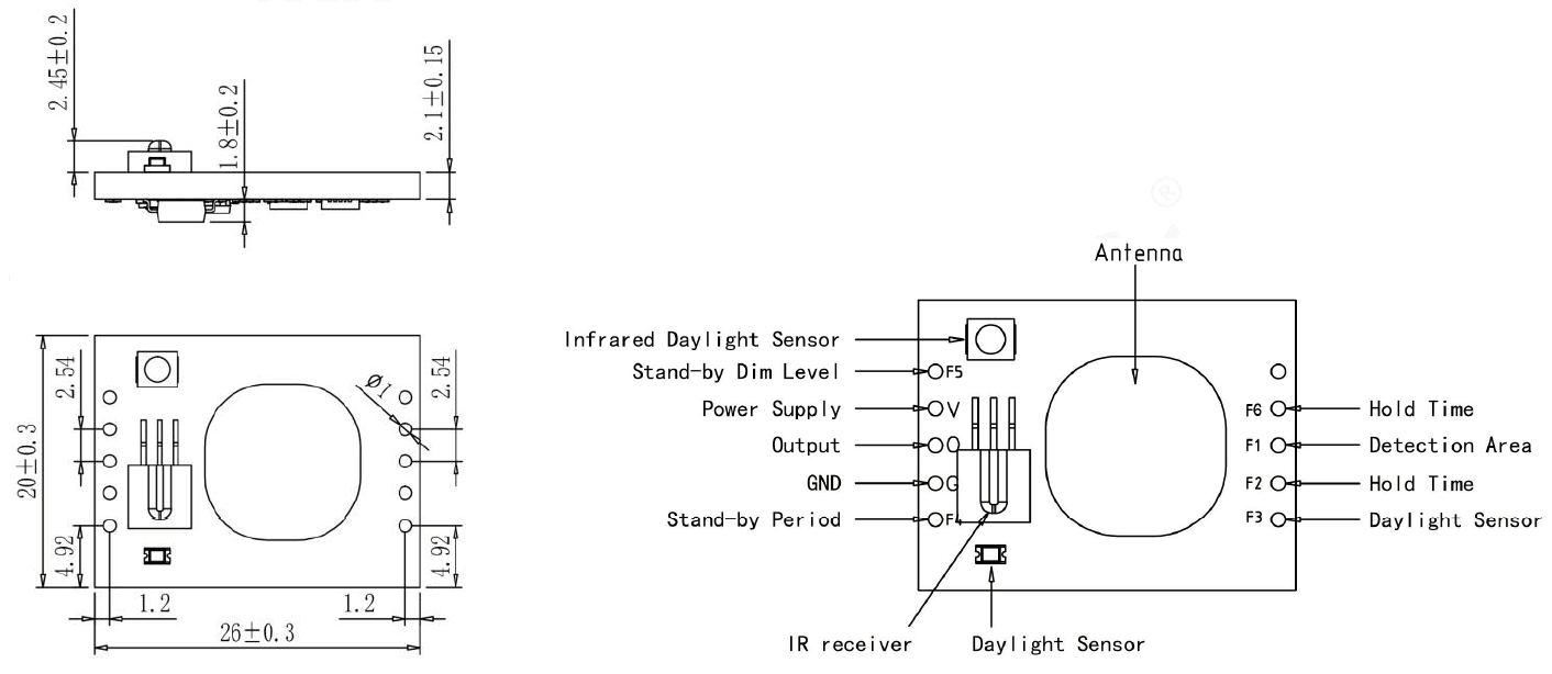
| Others | Connection | 4pin+5pin PinHeader | |||
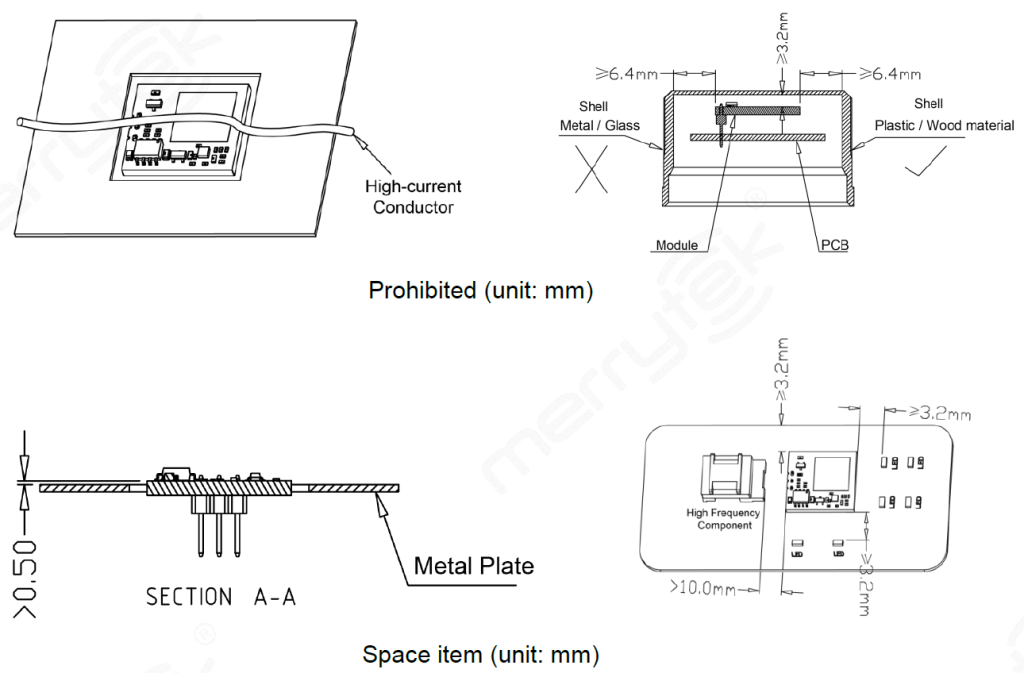
| Installation Requirement | Built in installation | ||||
| Packaging Requirements | Clapboard + Carton(K=A) | ||||
| Net Weight | 2±0.5g | ||||
| Lifetime | 5-year warranty@Ta | ||||
Default Setting
Detection Area: 25%, Hold time: 60min, Stand-by period: +∞, Stand-by DIM level: 30%, Daylight sensor: Disable
Initialization
The light will be turned on 100% brightness after power on, and self test for 5s. During initialization, no external motion sensing signal will be detected.
Application Notice
N/A